Installing all the gear for our home solar system was exciting–and a little daunting.
Planning things out ahead of time definitely helped but there were still a few areas where I had to make decisions on the fly. Great learning experience, for sure, and it all turned out nicely in the end, but in the middle of the process there were moments of doubt.
Underground Conduit
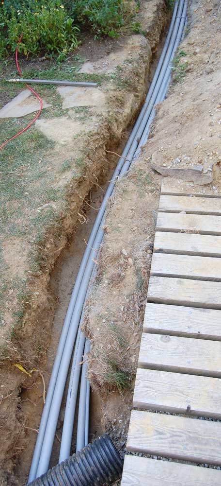
We buried all the power when we built the house, so in keeping with that theme I had a little digging to in order to run conduit from the house to the shed. It’s only a 40-foot shot from the service entrance on the house to the front wall of the shed, so I ended up just doing this by hand (with a little help from the progeny). A pickaxe and shovel made pretty quick work of it, but to be code-compliant the trench needed to be 36″ below grade, and I planned to bury 5 runs of conduit, so when all was said and done we moved some dirt. I lay the conduit down on a bed of sand, and covered it with another foot of sand before backfilling with original material (over the obligatory warning tape, of course!).
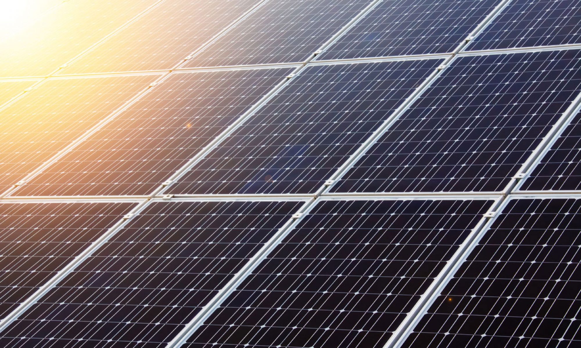
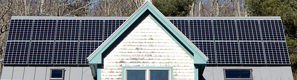
Rooftop Racking
It was early fall when I started planning things in earnest, and the panels arrived in late September. I was keen to get those mounted and secured ASAP so nobody was on the roof during cold drizzle and potential ice that can start to show up around Halloween. Following the lead of most of the local installers in the area, I used the SnapNRack system for mounting the modules. They didn’t have a clamp suited to my roof’s standing seam folds so I used S5! clamps instead at SnapNRack’s recommendation. My roofers, a very professional local outfit out of Waterville named CO Beck, used these very clamps for their snowguards, so it seemed like a good bet. Not cheap! But well worth it if there’s no worry about a rack losing its grip.
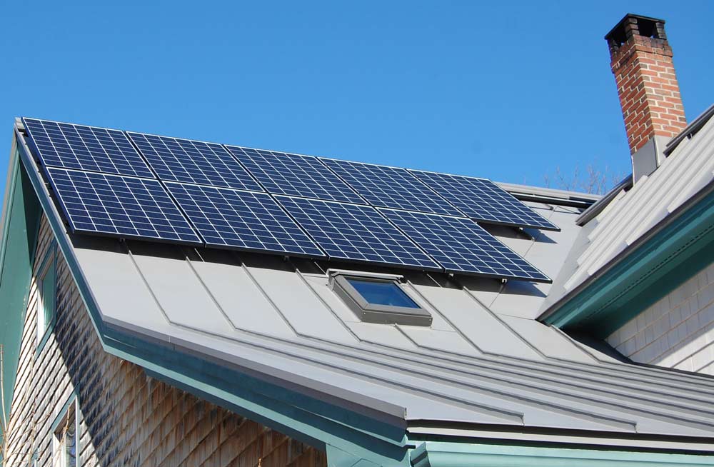
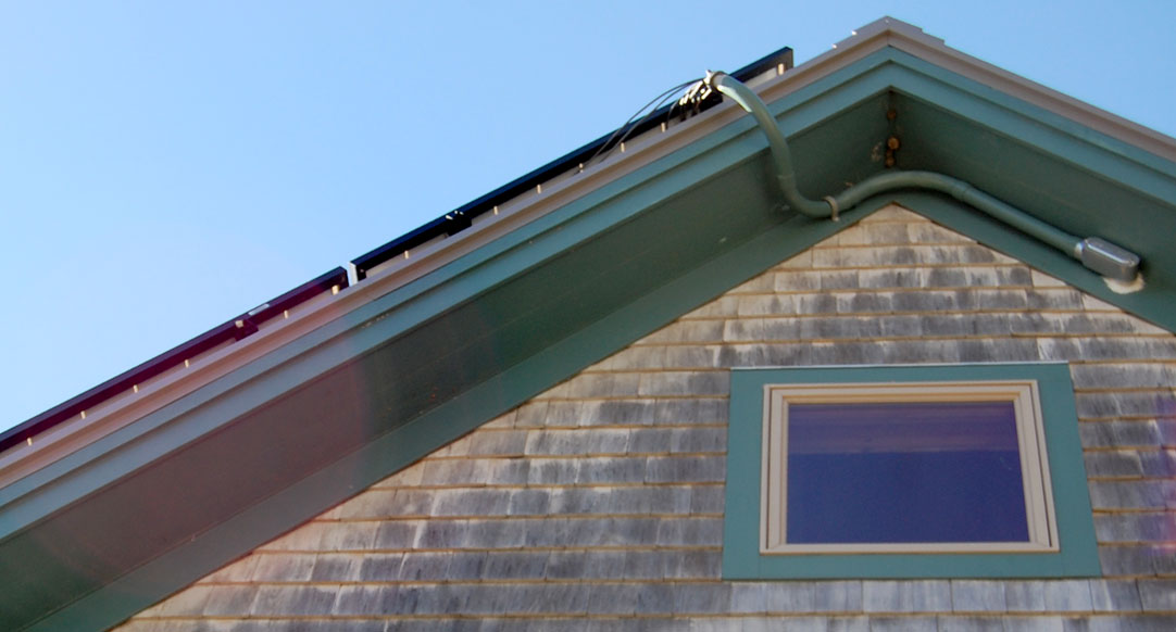
The racks went on pretty smoothly. Getting the layout planned on paper and marking it carefully in the field is key. I positioned the uppermost rail such that the panel would end up being a good half foot below the peak of the roof–no need to give those northerly wind gusts full purchase on the backside of the panels. With all the racks leveled out by stringline, I installed the rooftop wiring. The primary wire mostly ran inside the rail channels and led to a 2 1/2″ Schedule 40 conduit at the roof edge that brings the wires under the gable eave and into the attic wall.
Combiner Box and Disconnect Switch
I mounted a combiner box and disconnect switch on the inside wall just below where the conduit enters (switching to metal conduit where the conduit enters the wall. Pulling those 6 pairs of wires (plus the #8 bare copper equipment ground) through two 90 degree elbows was actually one of the more challenging tasks of the project. Let’s just say that the lubricant was priceless (I used Klein) and a few words common in the Navy may have been used during the process. Definitely need someone pushing and someone pulling.
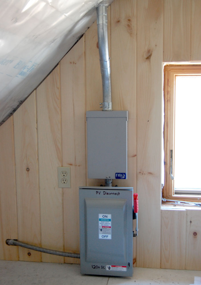
The combiner box in the attic is a Midnight Solar 6-breaker variety (MNPV6), and the disconnect is a Siemens HNF362PV, rated for 60A/600V DC. The combiner can be configured in several ways–for my purposes, it worked best to combine 3 strings into one array circuit feeding one charge controller and the other 3 strings into another circuit feeding the second controller. The disconnect switch is an important safety device and by code must be within 10 feet of the array. Strictly speaking the NEC now requires a “rapid shutdown” device triggered from the building exterior that electrically isolates the array from the rest of the system, but there’s been some controversy around this topic (a good subject for a future blog post) and our CEO was fine with just the disconnect switch in the attic. As someone experienced with structural firefighting, I can confidently say the odds of a rooftop vent operation in the array is nil, and the rest of the electrical system can be isolated from any current quite easily.
Installing the Solar Panels
After getting all the racking up and the primary array wiring installed, it was time to sling some panels. The plan was to get a helper and work as a pair–unfortunately that didn’t work out as hoped and I ended up doing the installation largely solo (with some help from my wife handing the panels to me on the roof). This wasn’t ideal, but I needed to get it done. I was roped off the entire time, and built a handy wooden jig to hold the panels in place while I fastened them, but still–it’s not easy handling those unwieldly modules by yourself on the roof. Fortunately the only casualty was a module backsheet that got a small ding from the corner of a standing seam, easily repairable (that one became the spare panel). I kept the panels covered with cardboard during installation to avoid any electrical issues. This was definitely the most stressful part of the install–I’m sure having another set of hands up and that roof would have helped immensely. But, all’s well that ends well–everything go put where it needed to go and nobody got hurt!
Wiring and Electrical Components
With the panels up and safely wired to the open breaker switches, I could stop eyeing the weather and focus on getting the wiring and electrical components installed. I ended up running a bundle of metal-clad cable containing four 4-gauge THWN-2 wires plus an insulated 6-gauge ground wire from the disconnect box in the attic to the utility room, since DC wiring inside homes needs to be enclosed in metal and I had naively installed schedule 40 at construction time (although that ended up working great for pulling the MC cable). The rest of the wiring was plain THWN-2, required by code for underground conduit. After calling around locally, it ended up being simpler and a little less expensive to order it online from Wire & Cable Your Way–everything arrived by freight in just a few days. I must say, it did surprise me how much just the wire itself added to the project budget (over $1K!), but copper ain’t cheap and 4 or 6 gauge wire has a lot of it.
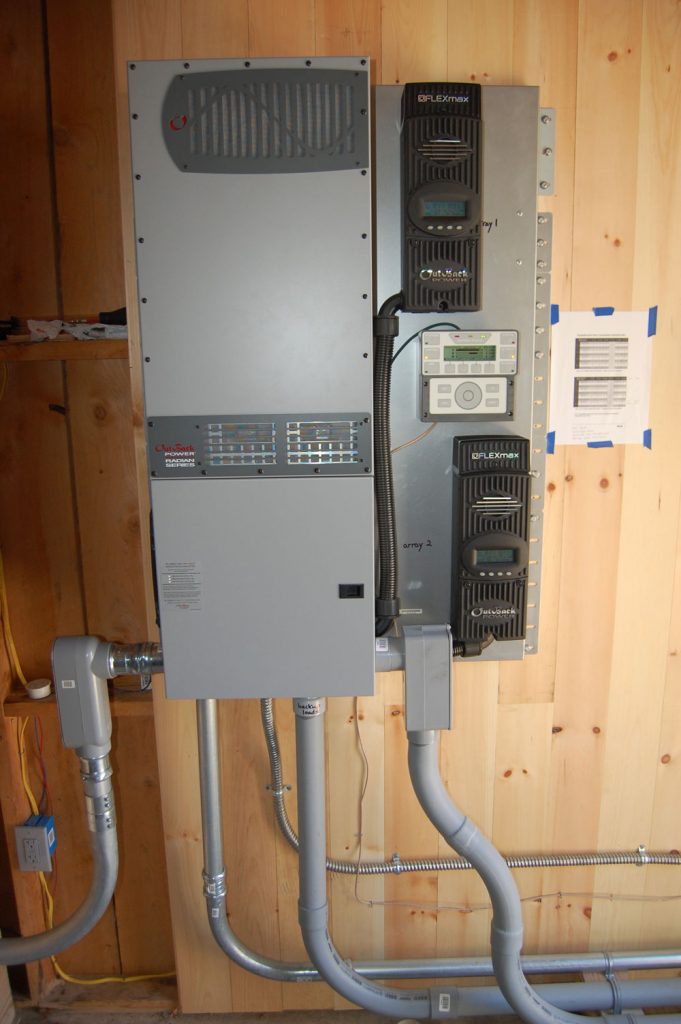
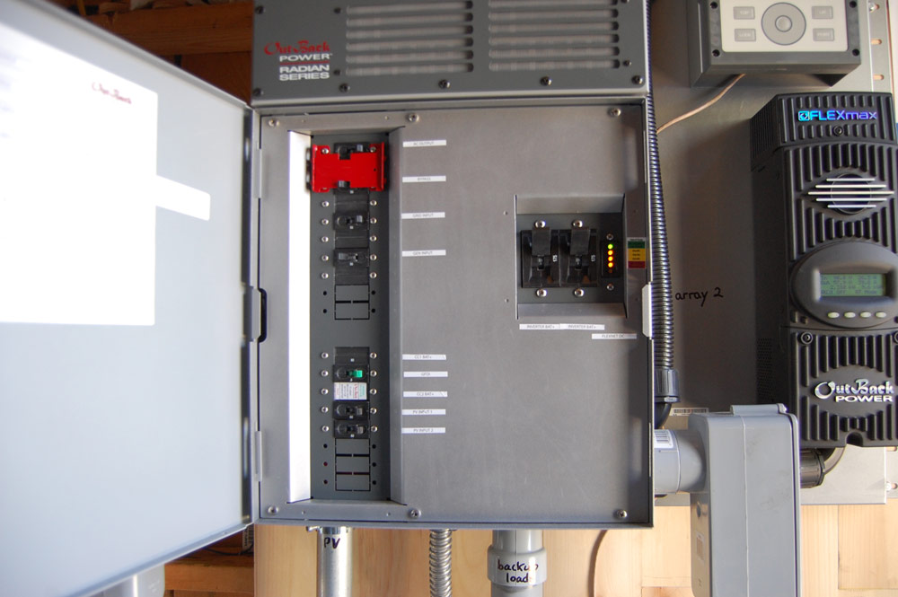
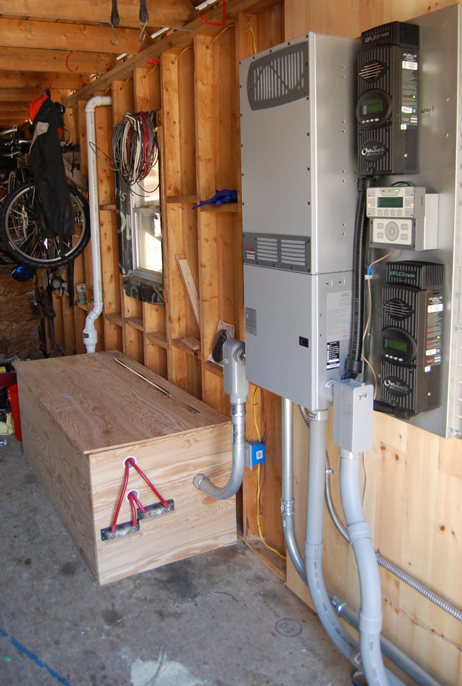
The inverter, charge controllers, and “control panel” assembly came all assembled onto a metal panel that mounts to the wall. This puppy was heavy, to say the least–it took three of us to get it in position on the wall. The mounting system was well-designed, however, and 1/4″ lag screws hold it securely. The large wiring panel where the breakers are mounted and the wiring buses are contained make for a very neat installation.
Like most inverters that can send power to the grid as well as provide backup power to the home during a grid blackout, this one has one circuit connecting it to the home’s main service panel and another feeding a separate, stand-alone distribution panel that powers the home’s “critical” or “backup” loads. For our critical loads panel I ended up just using a modest Square D QO612L100DF, which is small but big enough to manage the well pump, refrigerator, freezer, water heater, internet modem and router, plus a few lights and outlets. I mounted this right beside the home’s main service panel in our utility room.
Pulling the wire through the conduit runs wasn’t too hard–I used a shop-vac to pull a string with a crumbled scrap of plastic tied on the end through the conduit, then pulled a stout rope through to pull the actual wire bundles. Having someone pull while the other feeds is key; so is plenty of lubricant.
Once all the wire was pulled, making all the terminal connections was pretty straightforward. The Outback Load Center wiring box, which sits just below the inverter in the preassembled FlexPower unit, makes it very easy to terminate all the wiring at the inverter. Afterward I made sure to test everything for continuity or accidental grounds but found no issues.
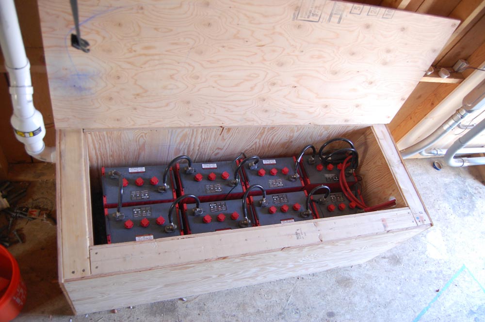
Battery Bank
To house the battery bank, I built a wood-framed box sheathed with half-inch plywood and mechanically ventilated with a programmable fan (the Outback Radian has a 12V auxiliary circuit made for this application). The Outback specs call for two pairs of 00 gauge battery cables (I used ones made by AltE, not cheap but very good quality), so I was a little worried about how that much copper and heavy insulation would pull through an elbow of 2″ metal conduit between the battery bank box and the inverter, but it wasn’t bad. I was advised to fuse the positive cables as close to the battery bank as possible (as a precaution in case of a short between the bank and the breakers at the inverter), so I put in fuse blocks on the outside of the box (as required) and routed a 2′ long pair of positive cables from the positive terminal out of the box to the fuse blocks, then the main pair to the inverter back into the box and through the conduit. Given how stiff 00 cable is, and the required bend radius, this operation was pretty tricky, but fortunately it all worked out fine. I think I got a little lucky in the placement of everything–be sure to plan this all out carefully, including checking your required bends with actual cable, before you start drilling holes or installing conduit!
Final Inspection
After checking the entire system over backwards and forwards visually, checking all terminal connections for looseness, and testing each circuit individually with a multi-meter, I invited our town Code Enforcement Officer over for a look (but not before installing all the required labels and signage!). He was perfectly happy with the installation and we passed with no issues. The final step before commissioning was to have the electrician who originally wired our house have a look at all the new work (that was supposed to happen before the CEO came but the electrician was too busy). Although I tried to be careful and do quality work, I’m not a licensed electrician and wanted an expert set of eyes on everything. He thought everything looked fine, but did find several terminal screws he was able to tighten further and also checked the factory-installed screws in the disconnect boxes, which I hadn’t thought of. I had several question for him as well so it was good to have an expert on hand.
It was December by the time the electrician came around, so while we didn’t meet the goal of commissioning before Thanksgiving, it looked like we’d be churning out solar watts by Christmas. I certainly didn’t break any speed records on the installation, but learned a huge amount about solar systems and I was pleased with the end result. Time now to turn everything on see if it actually works!